
Turnout Control from Servo Tester
A modified servo tester used to control a servo. By turning the potentiometer the direction of movement can be controlled as well as the distance. One side will always be a fixed position.
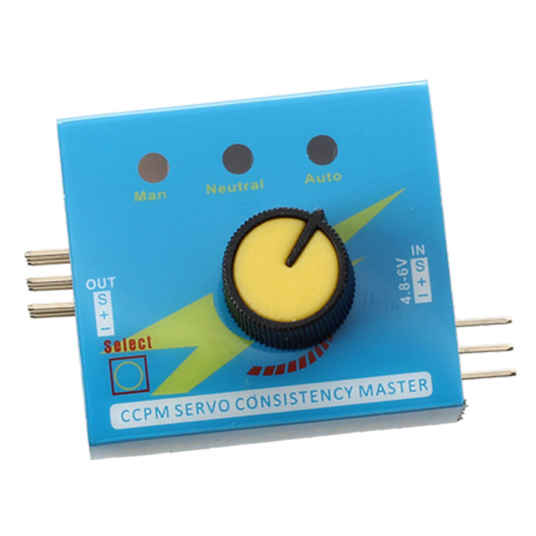
If you only need to control one or two turnouts there here is an inexpensive way to activate a servo. It is based on a servo tester that is very affordable. We have then on our store page for $2.99. Add an DpSt switch for turnout control or DpDt if you want leds as well. You’ll also need a couple of 5K resistors.

The first thing to do is remove the cover. Pull the knob off and the cover comes together in the front with a piece of adhesive. Gently separate the folded over portion. The cover can then be removed from the board.

On the bottom of the board, next to the section where nine servo pins are mounted, are the 3 solder joints for the potentiometer. The center joint is the connection for the wiper and the one we will modify. Apply heat from a soldering iron on the joint while prying the center leg up from on top of the board.

After the leg is out of the hole, fold the leg back to distance it from the servo connector pins. Solder a wire to the leg being careful not to form a bridge to the connector pin across from it. After soldering it would be a good idea to place a piece of electrical tape between the pins and the leg.

From underneath, solder a wire to the vacated hole where the leg was.

Solder a Ground wire. I found a good spot was back from the connecting pin.

The last wire we will solder is a 5 volt wire. Back from the connecting pin is a spot with a fairly large solder land that can be used.

Refer to the diagram for connecting a DpSt switch. The center post gets connected to the solder land on the bottom of the board where the Pot Leg was connected. One outside post on the switch gets connected to the Pot Leg on top of the board. On the last post of the switch, connect one leg of each of the two 5k resistors. That leaves the two leads off the resistors to connect. One resistor lead goes to 5 volts and the other leg goes to ground. When the switch is in one position, the servo will be close to mid point. In the other position, the Pot will determine the servo position. When installing, use the mid position to push the points to one rail and adjust the pot for the other rail position.

Since we have 5 volts and a ground, by changing the switch to a DPDT and adding a 220 ohm resistor and a red and green led, indicator lights can be added. Refer to the diagram. The center post of the 3 new posts goes to 5 volts. Be sure the connection is before the resistor. Each of the outer posts goes to the positive side of the LED. The negative sides connect together and then connect to a 220 ohm resistor. This is to drop the voltage down from 5 volts to around 3 which is what leds need. The other side of the resistor goes to ground. Now there are indicator lights.